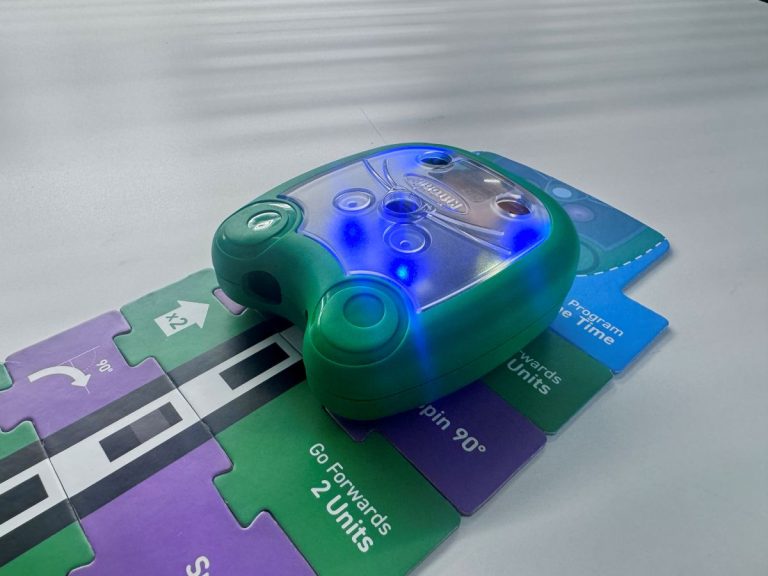
First Mai-Z the MouseBot Boxing (and unboxing!)
This wasn’t staged, but here’s our first Mai-Z the MouseBot shipment…. https://youtu.be/xRsZ6nPot8A …and her arrival in Louisiana! https://youtu.be/XHxRJQSpEUo


This wasn’t staged, but here’s our first Mai-Z the MouseBot shipment…. https://youtu.be/xRsZ6nPot8A …and her arrival in Louisiana! https://youtu.be/XHxRJQSpEUo
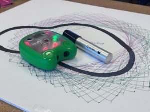
https://youtu.be/zn7boiDe3zA Wide-tip Permanent Marker (Sharpie) A popular classroom activity for Mai-Z the MouseBot is line following. My preference for creating the line is using a
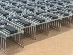
As I walked through our manufacturing facility today, the oven door was open and we were baking a fresh batch of BASIC Stamp 2 modules.

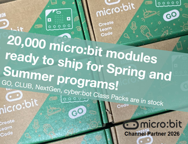
https://youtu.be/cxrjtwve5po The above YouTube micro:bit LIVE California Playlist includes over 45 videos! YouTube Playlist of micro:bit LIVE California No-script Clips Presentations and Photos from micro:bit
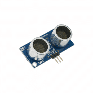
Hi Ken….is the PING))) Ultrasonic Sensor and “Roaming with PING” Arduino Code a good fit to program a Sheild-Bot to pass through a maze? Thank
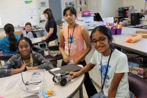
Hello Parallax, We hope you are well! Thank you so much for all your support for this year’s Summit. Your generous donation helped us host